Fireplace Heater PatentHeater and Mantel UnitHeaterGrille and Heating FluesGas Log HeaterGas Mixing UnitPortable Heating UnitGas BurnersMultiple Flue HeaterHeater GrilleCombo Heating StructureAir Flue for Refrigeration Refrigerator DisplayRefrigerator CaseHeater and Mantel UnitFireplace Heater PatentSALA PATENTSFireplace Heater PatentPatented June 10, 1924. 1,497,123UNITED STATES PATENT OFFICE.THEODORE A. SALA, OF DALLAS, TEXAS.FIREPLACE HEATERApplication filed March 19, 1923. Serial No. 625,969.To all whom it may concern:Be it know that I, THEODORE A. SALA, citizen of the United States of America, residing at Dallas, in the county of Dallas and State of Texas have invented certain new and useful Improvements in Fireplace Heaters, of which the following is a specification.This invention relates to new and useful improvements in heating devices.The object of the invention is to provide a heater which may be used in conjunction with a fire place and a mantel.A particular object of the invention is to provide a heater which may be built into a mantel or around which a mantel may be built and an attractive fire place produced.A further object of the invention is to provide a heater of the character described whereby heat units from a central fire place may be delivered on each side of the mantel structure, together with such air as passes through the fire place and is warmed.Another object of the invention is to proved a heater in which the heat units are diverted to each side and delivered into the room, together with air flues for admitting and conducting air contiguous to the passage of the heat units without contact therewith, whereby the air is warmed and so discharged into the room; such a method enhancing the circulation and promoting a more even temperature.A construction designed to carry out the invention will be hereinafter described together with other features of the invention. The invention will be more readily understood from a reading of the following specification and by reference to the accompanying drawings, in which an example of the invention is shown and wherein:Fig. 1 is a front elevation of a device constructed in accordance with my invention, a portion of the mantel being in section,Fig. 2 is a vertical sectional view of the upper portion of the heater,Fig. 3 is a side elevation of the device, the mantel being in section,Fig. 4 is a transverse vertical sectional view,Fig. 5 is a plan view.Fig. 6 is a modified form, a portion being illustrated in section,Fig. 7 is an end elevation, andFig. 8 is a transverse vertical sectional view.In the drawings the numeral 10 designates a fire box having an open front and which may be formed of sheet metal or which may be cast. The side and back wall of this box may be lined with a suitable fire resisting material if desired. The box is surrounded on each side and on the back by a vertical air flue 11.A transverse drum 12 is mounted on the fire box and is rectangular in cross-section, having its greatest dimension vertically. The drum communitcates with the air flue. Within the drum and spaced from 70 its side walls are a pair of diverging heat conducting flues 13, each having an upward curved top wall 14. These top walls have their lower inner ends meeting at the center of the drum over the center of the fire box. Within the air flues are arranged transverse spaced partitions 15 having their inner ends terminating in stepped order so as to be spaced at substantially equal distances from the top walls 14. The spacing 80 and stepping of these partitions may be varied to suit the conditions.At the outer end of each side of the drum is arranged a vertical grille 16, each having a frame 17 registering with the end of the heat flues 13 contiguous thereto. It will be seen that the heat units rising from the fire box pass directly into the flues 13 without entering the drum. A grille 18 surrounds the front of the fire box and covers the front of the air flue 11 so as to the pressent and ornamental apperance.A suitable gas fire maintained by a heater of the Bunsen burner type, such as will not give off objectionable fumes, is operated in the fire box. But other kinds of burners and heaters may be used in the fire box. In order to retard and deflect the heat units I arrange a pair of spaced deflector plates 19 transversely at the upper end of the fire box. These plates have perforations 20, those of one plate being in staggered relation to those of the other plates.It is the aim of this invention to installPatent # 01497123this heating device in a chimney breast or mantel 21 and to have the grilles 16 on the sides of the mantel structure. An advantage is that no chimney is required and therefore a very attractive and ornamental fire place and mantel may be built in a room without a chimney. Further the heated air is delivered on each side of the mantel and a better distribution is had.The heat units from the fire box will pass up through the perforations 20 and into each of the flues 13.The partitions 15 will divert the units and distribute the same to the grilles 16 from which they will pass into the room. Air entering the grille 18 will be received into flue 11 and thus warmed without coming into contact with the heater or promoting a draft therearound. The warm air rises in the flue 11 and passes into the drum where its temperature is raised by contact with the walls of the flue 13. This warm air passes through the grilles 16 and escapes into the room. The air flues and the drum maintain moving air currents around the fire box and the flue 13 and prevent excessive heating of the same, thereby reducing the fire hazard. The heat units and the heated air passing into the room will set up a circulation therein, whereby all of the air in the room will be handled and a more even temperature maintained.The heating device being made in a unit construction may be readily installed in the mantel without tearing up the floor and the mantel may be built in a corner or against a wall.In Figs. 6 and 7 I have shown a modified form in which I employ a vertical fire box 10' constructed of suitable material and lined with fire resisting material if desired. On top of the box is mounted a transverse drum overhanging the box on each side and extending the width of the mantel 21'. In each end of the drum is mounted a grille 16' secured to the face of the side wall of the mantel. If desired a baffle plate 19' may be mounted at the top of the fire box, but this is not essential. Also in the drum may be arranged longitudinal partitions 15' having their inner ends overhanging each other slipped over the fire box, but these may be omitted.By reason of the drum extending through the mantel and having grilles at each sied of the said mantel, the drum is concealed and the front of the mantel is not defaced. An attractive fire place may be produced and an effective heater provided. The heat units and warm air being discharged on each side of the mantel will more effectively heat the room and maintain a circulation.Various changes in the parts such as the addition of suitable dampers and otherchanges and alterations may be made within the scope of the claims and without departing from the spirit of the invention.What I claim, is:1. In a heating device, a fire box, an air flue contiguous to the sides of the fire box, a horizontal drum over the fire box, heat flues extending longitudinally through the drum and connected with the fire box, the air flue having connection with the drum separately from the fire box, the drum having air passages free from communication with the heat flues but connected with the air flue, the drum having outlets at its sides.2. In a heating device, the combination with a chimney breast having a fire place, of a fire box arranged in the fire place, a vertical air flue in the fire place contiguous to the fire box, a horizontal air drum extending transversely through the chimney breast grilles at the ends of the drum on the sides of the chimney breast, and diverging heat flues extending longitudinally of the drum and connected with the fire box, the air flue being connected with the drum but being free from connection with the fire box or the heat flues.3. In a heating device, the combination with a chimney breast having a fire place, of a fire box arranged in the fire place, a vertical air flue in the fire place contiguous to the fire box, a horizontal air drum extending transversely through the chimney breast grilles at the ends of the drum on the sides of the chimney breast, and diverging heat flues extending longitudinally of the drum and connected with the fire box, the air flue being connected with the drum but being free from connection with the fire box or the heat flues, and a grille at the front of the air flue and fire box.4. In a heating device for fire-places, a vertical fire box having an open front, a vertical air flue surrounding the sides and back of the fire box but free from communication therewith, a tranverse drum mounted on the fire box and extending beyond the same on each side, diverging heat flues mounted in the drum and extending from the fire box to each end thereof, air passages in the drum communication with the air flue but free from connection with the heat flues, tranverse partitions in the heat flues, and a baffle between the fire box and the heat flues.5. In a heating device, the combination with a chimney breast having a fire place, of a vertical fire box arranged in the fire place, a vertical air flue contiguous to the fire box, a horizontal drum extending tranversely through the chimney breast and connected with the air flue, a heat flue extending longitudinally of the drum, and portions mounted in the drum having theirinner ends in stepped order, the drum having outlets at its sides.6. In a heating device, the combination with a chimney breast having a fire place, a vertical fire box arranged in the fire place, and a transverse drum extending entirely through the chimney breast and connectedwith the fire box, the drum being concealed in the chimney breast and having its ends exposed on each side of the chimney breast for discharging warm air into a room.In testimony whereof I affix my signature.THEODORE A. SALA.HistorySala Heater and Mantel Co.Go Back to: History of Sala HeatersGo Back to: Sala PatentsCALL TODAY! 214-742-7252Dallas Air Conditioning RepairAIR CONDITIONING SERVICE DALLAS TXHome | Products | Services | Coupons | Contracting | Contact | News Blog | Service Area | About Us |SitemapService Areas: Dallas, Duncanville, DeSoto, Cedar Hill, Lancaster, Highland Park, Grand Prairie, Carrollton, Irving, Addison, Garland, Coppell, Southlake, Grapevine, Sunnyvale, Richardson, Farmers Branch, Allen, Parker, Lucas, Frisco, Lewisville, Flower Mound, Rowlett, Rockwall, Sachse, The Colony, University Park, Wylie, Murphy, Mansfield, Mesquite, Midlothian, Ovilla, Red Oak, Hutchins, Lake Highlands, Lakewood, Preston Hollow, Oak Lawn, and Plano


 Fireplace Heater Patent
 Heater and Mantel Unit
 Heater
 Grille and Heating Flues
 Gas Log Heater

 Gas Mixing Unit
 Portable Heating Unit
 Gas Burners

 Multiple Flue Heater
 Heater Grille
Combo Heating Structure
Heater Grille
Combo Heating Structure
 Air Flue for Refrigeration
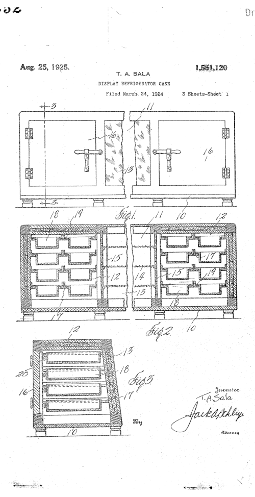
 Refrigerator Display
 Refrigerator Case
 Heater and Mantel Unit
Fireplace Heater Patent
SALA PATENTS
Fireplace Heater Patent
Heater and Mantel Unit
Fireplace Heater Patent
SALA PATENTS
Fireplace Heater Patent

 Patented June 10, 1924. 1,497,123
UNITED STATES PATENT OFFICE.
THEODORE A. SALA, OF DALLAS, TEXAS.
FIREPLACE HEATER
Application filed March 19, 1923. Serial No. 625,969.
To all whom it may concern:
Be it know that I, THEODORE A. SALA, citizen of
the United States of America, residing at Dallas, in the
county of Dallas and State of Texas have invented
certain new and useful Improvements in Fireplace
Heaters, of which the following is a specification.
This invention relates to new and useful
improvements in heating devices.
The object of the invention is to provide a heater
which may be used in conjunction with a fire place and
a mantel.
A particular object of the invention is to provide a
heater which may be built into a mantel or around which
a mantel may be built and an attractive fire place
produced.
A further object of the invention is to provide a
heater of the character described whereby heat units
from a central fire place may be delivered on each side
of the mantel structure, together with such air as
passes through the fire place and is warmed.
Another object of the invention is to proved a
heater in which the heat units are diverted to each side
and delivered into the room, together with air flues for
admitting and conducting air contiguous to the passage
of the heat units without contact therewith, whereby the
air is warmed and so discharged into the room; such a
method enhancing the circulation and promoting a more
even temperature.
A construction designed to carry out the invention
will be hereinafter described together with other
features of the invention.
The invention will be more readily understood
from a reading of the following specification and by
reference to the accompanying drawings, in which an
example of the invention is shown and wherein:
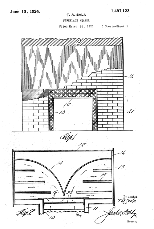
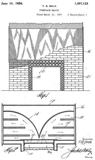
Fig. 1 is a front elevation of a device constructed
in accordance with my invention, a portion of the mantel
being in section,
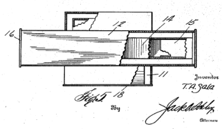
Fig. 2 is a vertical sectional view of the upper
portion of the heater,
Fig. 3 is a side elevation of the device, the
mantel being in section,
Fig. 4 is a transverse vertical sectional view,
Fig. 5 is a plan view.
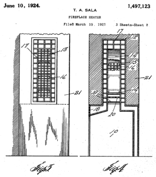
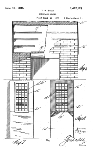
Fig. 6 is a modified form, a portion being
illustrated in section,
Fig. 7 is an end elevation, and
Fig. 8 is a transverse vertical sectional view.
In the drawings the numeral 10 designates a fire
box having an open front and which may be formed of
sheet metal or which may be cast. The side and back
wall of this box may be lined with a suitable fire
resisting material if desired. The box is surrounded on
each side and on the back by a vertical air flue 11.
A transverse drum 12 is mounted on the fire box
and is rectangular in cross-section, having its greatest
dimension vertically. The drum communitcates with the
air flue. Within the drum and spaced from 70 its side
walls are a pair of diverging heat conducting flues 13,
each having an upward curved top wall 14. These top
walls have their lower inner ends meeting at the center
of the drum over the center of the fire box. Within the air
flues are arranged transverse spaced partitions 15
having their inner ends terminating in stepped order so
as to be spaced at substantially equal distances from
the top walls 14. The spacing 80 and stepping of these
partitions may be varied to suit the conditions.
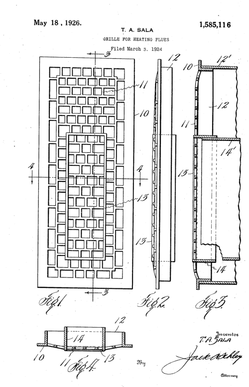
At the outer end of each side of the drum is
arranged a vertical grille 16, each having a frame 17
registering with the end of the heat flues 13 contiguous
thereto. It will be seen that the heat units rising from the
fire box pass directly into the flues 13 without entering
the drum. A grille 18 surrounds the front of the fire box
and covers the front of the air flue 11 so as to the
pressent and ornamental apperance.
A suitable gas fire maintained by a heater of the
Bunsen burner type, such as will not give off
objectionable fumes, is operated in the fire box. But
other kinds of burners and heaters may be used in the
fire box. In order to retard and deflect the heat units I
arrange a pair of spaced deflector plates 19
transversely at the upper end of the fire box. These
plates have perforations 20, those of one plate being in
staggered relation to those of the other plates.
It is the aim of this invention to install
Patented June 10, 1924. 1,497,123
UNITED STATES PATENT OFFICE.
THEODORE A. SALA, OF DALLAS, TEXAS.
FIREPLACE HEATER
Application filed March 19, 1923. Serial No. 625,969.
To all whom it may concern:
Be it know that I, THEODORE A. SALA, citizen of
the United States of America, residing at Dallas, in the
county of Dallas and State of Texas have invented
certain new and useful Improvements in Fireplace
Heaters, of which the following is a specification.
This invention relates to new and useful
improvements in heating devices.
The object of the invention is to provide a heater
which may be used in conjunction with a fire place and
a mantel.
A particular object of the invention is to provide a
heater which may be built into a mantel or around which
a mantel may be built and an attractive fire place
produced.
A further object of the invention is to provide a
heater of the character described whereby heat units
from a central fire place may be delivered on each side
of the mantel structure, together with such air as
passes through the fire place and is warmed.
Another object of the invention is to proved a
heater in which the heat units are diverted to each side
and delivered into the room, together with air flues for
admitting and conducting air contiguous to the passage
of the heat units without contact therewith, whereby the
air is warmed and so discharged into the room; such a
method enhancing the circulation and promoting a more
even temperature.
A construction designed to carry out the invention
will be hereinafter described together with other
features of the invention.
The invention will be more readily understood
from a reading of the following specification and by
reference to the accompanying drawings, in which an
example of the invention is shown and wherein:
Fig. 1 is a front elevation of a device constructed
in accordance with my invention, a portion of the mantel
being in section,
Fig. 2 is a vertical sectional view of the upper
portion of the heater,
Fig. 3 is a side elevation of the device, the
mantel being in section,
Fig. 4 is a transverse vertical sectional view,
Fig. 5 is a plan view.
Fig. 6 is a modified form, a portion being
illustrated in section,
Fig. 7 is an end elevation, and
Fig. 8 is a transverse vertical sectional view.
In the drawings the numeral 10 designates a fire
box having an open front and which may be formed of
sheet metal or which may be cast. The side and back
wall of this box may be lined with a suitable fire
resisting material if desired. The box is surrounded on
each side and on the back by a vertical air flue 11.
A transverse drum 12 is mounted on the fire box
and is rectangular in cross-section, having its greatest
dimension vertically. The drum communitcates with the
air flue. Within the drum and spaced from 70 its side
walls are a pair of diverging heat conducting flues 13,
each having an upward curved top wall 14. These top
walls have their lower inner ends meeting at the center
of the drum over the center of the fire box. Within the air
flues are arranged transverse spaced partitions 15
having their inner ends terminating in stepped order so
as to be spaced at substantially equal distances from
the top walls 14. The spacing 80 and stepping of these
partitions may be varied to suit the conditions.
At the outer end of each side of the drum is
arranged a vertical grille 16, each having a frame 17
registering with the end of the heat flues 13 contiguous
thereto. It will be seen that the heat units rising from the
fire box pass directly into the flues 13 without entering
the drum. A grille 18 surrounds the front of the fire box
and covers the front of the air flue 11 so as to the
pressent and ornamental apperance.
A suitable gas fire maintained by a heater of the
Bunsen burner type, such as will not give off
objectionable fumes, is operated in the fire box. But
other kinds of burners and heaters may be used in the
fire box. In order to retard and deflect the heat units I
arrange a pair of spaced deflector plates 19
transversely at the upper end of the fire box. These
plates have perforations 20, those of one plate being in
staggered relation to those of the other plates.
It is the aim of this invention to install


 Patent # 01497123
this heating device in a chimney breast or mantel
21 and to have the grilles 16 on the sides of the mantel
structure. An advantage is that no chimney is required
and therefore a very attractive and ornamental fire place
and mantel may be built in a room without a chimney.
Further the heated air is delivered on each side of the
mantel and a better distribution is had.
The heat units from the fire box will pass up
through the perforations 20 and into each of the flues
13.
The partitions 15 will divert the units and
distribute the same to the grilles 16 from which they will
pass into the room. Air entering the grille 18 will be
received into flue 11 and thus warmed without coming
into contact with the heater or promoting a draft
therearound. The warm air rises in the flue 11 and
passes into the drum where its temperature is raised by
contact with the walls of the flue 13. This warm air
passes through the grilles 16 and escapes into the
room. The air flues and the drum maintain moving air
currents around the fire box and the flue 13 and prevent
excessive heating of the same, thereby reducing the fire
hazard. The heat units and the heated air passing into
the room will set up a circulation therein, whereby all of
the air in the room will be handled and a more even
temperature maintained.
The heating device being made in a unit
construction may be readily installed in the mantel
without tearing up the floor and the mantel may be built
in a corner or against a wall.
In Figs. 6 and 7 I have shown a modified form in
which I employ a vertical fire box 10' constructed of
suitable material and lined with fire resisting material if
desired. On top of the box is mounted a transverse
drum overhanging the box on each side and extending
the width of the mantel 21'. In each end of the drum is
mounted a grille 16' secured to the face of the side wall
of the mantel. If desired a baffle plate 19' may be
mounted at the top of the fire box, but this is not
essential. Also in the drum may be arranged longitudinal
partitions 15' having their inner ends overhanging each
other slipped over the fire box, but these may be
omitted.
By reason of the drum extending through the
mantel and having grilles at each sied of the said
mantel, the drum is concealed and the front of the
mantel is not defaced. An attractive fire place may be
produced and an effective heater provided. The heat
units and warm air being discharged on each side of the
mantel will more effectively heat the room and maintain
a circulation.
Various changes in the parts such as the addition
of suitable dampers and other
changes and alterations may be made within the
scope of the claims and without departing from the spirit
of the invention.
What I claim, is:
1. In a heating device, a fire box, an air flue
contiguous to the sides of the fire box, a horizontal
drum over the fire box, heat flues extending
longitudinally through the drum and connected with the
fire box, the air flue having connection with the drum
separately from the fire box, the drum having air
passages free from communication with the heat flues
but connected with the air flue, the drum having outlets
at its sides.
2. In a heating device, the combination with a
chimney breast having a fire place, of a fire box
arranged in the fire place, a vertical air flue in the fire
place contiguous to the fire box, a horizontal air drum
extending transversely through the chimney breast
grilles at the ends of the drum on the sides of the
chimney breast, and diverging heat flues extending
longitudinally of the drum and connected with the fire
box, the air flue being connected with the drum but
being free from connection with the fire box or the heat
flues.
3. In a heating device, the combination with a
chimney breast having a fire place, of a fire box
arranged in the fire place, a vertical air flue in the fire
place contiguous to the fire box, a horizontal air drum
extending transversely through the chimney breast
grilles at the ends of the drum on the sides of the
chimney breast, and diverging heat flues extending
longitudinally of the drum and connected with the fire
box, the air flue being connected with the drum but
being free from connection with the fire box or the heat
flues, and a grille at the front of the air flue and fire box.
4. In a heating device for fire-places, a vertical
fire box having an open front, a vertical air flue
surrounding the sides and back of the fire box but free
from communication therewith, a tranverse drum
mounted on the fire box and extending beyond the
same on each side, diverging heat flues mounted in the
drum and extending from the fire box to each end
thereof, air passages in the drum communication with
the air flue but free from connection with the heat flues,
tranverse partitions in the heat flues, and a baffle
between the fire box and the heat flues.
5. In a heating device, the combination with a
chimney breast having a fire place, of a vertical fire box
arranged in the fire place, a vertical air flue contiguous
to the fire box, a horizontal drum extending tranversely
through the chimney breast and connected with the air
flue, a heat flue extending longitudinally of the drum,
and portions mounted in the drum having their
Patent # 01497123
this heating device in a chimney breast or mantel
21 and to have the grilles 16 on the sides of the mantel
structure. An advantage is that no chimney is required
and therefore a very attractive and ornamental fire place
and mantel may be built in a room without a chimney.
Further the heated air is delivered on each side of the
mantel and a better distribution is had.
The heat units from the fire box will pass up
through the perforations 20 and into each of the flues
13.
The partitions 15 will divert the units and
distribute the same to the grilles 16 from which they will
pass into the room. Air entering the grille 18 will be
received into flue 11 and thus warmed without coming
into contact with the heater or promoting a draft
therearound. The warm air rises in the flue 11 and
passes into the drum where its temperature is raised by
contact with the walls of the flue 13. This warm air
passes through the grilles 16 and escapes into the
room. The air flues and the drum maintain moving air
currents around the fire box and the flue 13 and prevent
excessive heating of the same, thereby reducing the fire
hazard. The heat units and the heated air passing into
the room will set up a circulation therein, whereby all of
the air in the room will be handled and a more even
temperature maintained.
The heating device being made in a unit
construction may be readily installed in the mantel
without tearing up the floor and the mantel may be built
in a corner or against a wall.
In Figs. 6 and 7 I have shown a modified form in
which I employ a vertical fire box 10' constructed of
suitable material and lined with fire resisting material if
desired. On top of the box is mounted a transverse
drum overhanging the box on each side and extending
the width of the mantel 21'. In each end of the drum is
mounted a grille 16' secured to the face of the side wall
of the mantel. If desired a baffle plate 19' may be
mounted at the top of the fire box, but this is not
essential. Also in the drum may be arranged longitudinal
partitions 15' having their inner ends overhanging each
other slipped over the fire box, but these may be
omitted.
By reason of the drum extending through the
mantel and having grilles at each sied of the said
mantel, the drum is concealed and the front of the
mantel is not defaced. An attractive fire place may be
produced and an effective heater provided. The heat
units and warm air being discharged on each side of the
mantel will more effectively heat the room and maintain
a circulation.
Various changes in the parts such as the addition
of suitable dampers and other
changes and alterations may be made within the
scope of the claims and without departing from the spirit
of the invention.
What I claim, is:
1. In a heating device, a fire box, an air flue
contiguous to the sides of the fire box, a horizontal
drum over the fire box, heat flues extending
longitudinally through the drum and connected with the
fire box, the air flue having connection with the drum
separately from the fire box, the drum having air
passages free from communication with the heat flues
but connected with the air flue, the drum having outlets
at its sides.
2. In a heating device, the combination with a
chimney breast having a fire place, of a fire box
arranged in the fire place, a vertical air flue in the fire
place contiguous to the fire box, a horizontal air drum
extending transversely through the chimney breast
grilles at the ends of the drum on the sides of the
chimney breast, and diverging heat flues extending
longitudinally of the drum and connected with the fire
box, the air flue being connected with the drum but
being free from connection with the fire box or the heat
flues.
3. In a heating device, the combination with a
chimney breast having a fire place, of a fire box
arranged in the fire place, a vertical air flue in the fire
place contiguous to the fire box, a horizontal air drum
extending transversely through the chimney breast
grilles at the ends of the drum on the sides of the
chimney breast, and diverging heat flues extending
longitudinally of the drum and connected with the fire
box, the air flue being connected with the drum but
being free from connection with the fire box or the heat
flues, and a grille at the front of the air flue and fire box.
4. In a heating device for fire-places, a vertical
fire box having an open front, a vertical air flue
surrounding the sides and back of the fire box but free
from communication therewith, a tranverse drum
mounted on the fire box and extending beyond the
same on each side, diverging heat flues mounted in the
drum and extending from the fire box to each end
thereof, air passages in the drum communication with
the air flue but free from connection with the heat flues,
tranverse partitions in the heat flues, and a baffle
between the fire box and the heat flues.
5. In a heating device, the combination with a
chimney breast having a fire place, of a vertical fire box
arranged in the fire place, a vertical air flue contiguous
to the fire box, a horizontal drum extending tranversely
through the chimney breast and connected with the air
flue, a heat flue extending longitudinally of the drum,
and portions mounted in the drum having their


 Home | Products | Services | Coupons | Contracting | Contact | News Blog | Service Area | About Us | Sitemap
Service Areas: Dallas, Duncanville, DeSoto, Cedar Hill, Lancaster, Highland Park, Grand Prairie, Carrollton, Irving, Addison,
Garland, Coppell, Southlake, Grapevine, Sunnyvale, Richardson, Farmers Branch, Allen, Parker, Lucas, Frisco, Lewisville,
Flower Mound, Rowlett, Rockwall, Sachse, The Colony, University Park, Wylie, Murphy, Mansfield, Mesquite, Midlothian,
Ovilla, Red Oak, Hutchins, Lake Highlands, Lakewood, Preston Hollow, Oak Lawn, and Plano
Home | Products | Services | Coupons | Contracting | Contact | News Blog | Service Area | About Us | Sitemap
Service Areas: Dallas, Duncanville, DeSoto, Cedar Hill, Lancaster, Highland Park, Grand Prairie, Carrollton, Irving, Addison,
Garland, Coppell, Southlake, Grapevine, Sunnyvale, Richardson, Farmers Branch, Allen, Parker, Lucas, Frisco, Lewisville,
Flower Mound, Rowlett, Rockwall, Sachse, The Colony, University Park, Wylie, Murphy, Mansfield, Mesquite, Midlothian,
Ovilla, Red Oak, Hutchins, Lake Highlands, Lakewood, Preston Hollow, Oak Lawn, and Plano