Fireplace Heater PatentHeater and Mantel UnitHeaterGrille and Heating FluesGas Log HeaterGas Mixing UnitPortable Heating UnitGas BurnersMultiple Flue HeaterHeater GrilleCombo Heating StructureAir Flue for Refrigeration Refrigerator DisplayRefrigerator CaseHeater and Mantel UnitFireplace Heater PatentSALA PATENTSRefrigerator Case PatentPatented August 25 ,1925. 1,551,120UNITED STATES PATENT OFFICE.THEODORE A. SALA, OF DALLAS, TEXAS.DISPLAY REFRIGERATOR CASEApplication filed March 24, 1924. Serial No. 701,299.To all whom it may concern:Be it know that I, THEODORE A. SALA, citizen of the United States of America, residing at Dallas, in the county of Dallas and State of Texas have invented certain new and useful Improvements in Display Refrigerator Cases, of which the following is a specification.This invention relates to new and useful improvements in display refrigerator cases.The invention has to do with that type of refrigerator which is generally used as a counter in stores and markets and comprises refrigerator compartments at end communication with an intermediate display chamber which occupies a major portion of the length of the case. It is customary to place shelves in these chambers and to use receptacles in the refrigerating compartments containing ice and brine water or other cooling solutions for making temperatures below freezing.These receptacles are generally comparatively large and but one is provided in each refrigerator compartment, for each compartment or section of the display chamber. As the cooling solution in the receptacle evaporates or is carried off, its level is lowered and the coldest air stratum being directly over the solution, consequently the upper portion of the refrigerator compartment becomes warm, as does the upper part of the display chamber. As the liquid solution level descends, the temperature at the top of the chamber rises. To lower the temperature the receptacle must be re-iced and even then there will be an area at the top of the display chamber which is not as cold as lower areas, because the receptacle may not reach the top of the refrigerator or it may not be filled to its top. These arrangements do not provide a uniform temperature in the display chamber, are not economical and fail to give as much efficiency as is obtainable.It is the object of my invention to provide means in the refrigerator compartment of a display refrigerator case, for maintaining a nearly uniform temperature below freezing or at the desired degree and for realizing as much benefit from the cooling solution, at the top as is received at the bottomof the refrigerator compartment and display chamber.A further object is to provide a plurality of comparatively small receptacles at different elevations in the refrigerating compartment, preferably regularly spaced or in close relation, whereby the cooling solution acts directly upon the circulating air equally at the top, center and bottom of the compartment; and whereby the receptacles may be interchanged from one elevaation to the other or individually re-iced all of which makes for greater efficiency and economy.A construction designed to carry out the invention will be hereinafter described together with other features of the invention.The invention will be more readily understood from a reading of the following specification and by reference to the accompanying drawings, in which an example of the invention is shown, and wherein:Fig. 1 is a fragmentary rear elevation of a case constructed in accordance with my invention,Fig. 2 is a longitudinal vertical sectional view of the same,Fig. 3 is a transverse vertical sectional view taken on the line 3-3 of Fig. 1,Fig. 4 is a rear elevation of a modified form,Fig. 5 is a longitudinal vertical sectional view of the same, Fig. 6 is a transverse vertical sectional view on the line 6-6 of Fig. 4,Fig. 7 is a fragmentary rear view of a modified form case, partly in elevation and partly in section, andFig. 8 is a transverse vertical sectional view on the lin 8-8 of Fig. 7.In the drawing the numberal 10 designates the base of a case which has a central or intermediate display chamber 11 of the usual type and refrigerating compartments 12 at each end, all having their tops flush to form a counter. The chamber 11 has a glass front 13 and may be provided with a plurality of superposed foraminous shelves 14, through which the air will circulate. Between each end of the display chamber 11 and the contiguous refrigerator compartment 12 is a vertical foraminous partition 15. Each compartment has a rear door 16,Patent # 01551120but one or more doors may be used. All of the parts which have been described are common in the art and no separate claim is made thereto.In carrying out the invention I mount a plurality of angular guide rails 17 transversely of each compartment 12 which extend from front to rear. These rails are mounted in pairs at different elevations, two pairs to each elevation. Between each pair of rails is suspended a drawer of rectangular receptacle 18 each having out-turned flanges 19 at its upper side edges, resting on the rails. Each drawer has a handle 20, by which it may be grasped and slid out the rear side of the compartment when the door 16 is open.This is true of all the figures of the drawings. In Figs 1 to 3 incluseive, I have shown eight drawers to a compartment, two at each elevation. These drawers are filled with any kind of a refrigeration solution or liquid, such as cracked ice and drine water and the like. It will be seen that the upper drawers are close to the top of the compartment, while the lower drawers are close to the bottom. The four intermediate drawers are spaced between the top and bottom drawers and provide a cooling influence for this area.All of the drawers supply the same compartment of the display chamber and there is just as much refrigeration at the top as there is at the bottom. This is important as the air cooled by the upper drawers circulates directly into the upper portion of the display chamber, thus cooling and maintaining a low temperature. Usually in a compartment such as I have illustrated two refrigerating receptacles are used. It will be seen that with such large receptacles, the level of the refrigerating liquid will be reduced by evaporation and a large upper space, without direct refrigeration, is constantly being made.Even with the drawers half filled with liquid direct refrigeration is had at the top of the compartments 12 and chamber 11. The drawers are all interchangeable. For instance after a period of time the top drawers may be interchanged with the bottom drawers, as the liquid in the top drawers may have a tendency to evaporate faster thatn the liquid in the bottom drawers. Any drawer ma be refilled and only one or two drawers may require refilling at a time. This is much more economical and efficient.The invention permits of considerable variation. For instance a butcher or store keeper may require more display and storage space on some days than on others, so that it will be economical to reduce the refrigerating space and the quantity of liquid used. In Figs. 4, 5 and 6 I have shown a case with a central longitudinallypartition 21, extending from end to end through the compartments 12, and the chamber 11. This partition divides the case into two units or sections, one above the other, other wise it is the same as that shown in Fig. 2. The four upper drawers in the upper sections of the compartments 12 refrigerate the upper section of the chamber 11, while the four lower drawers refrigerate the lower section of the chamber. However both the upper and lower sections of the chamber have direct refrigeration at the upper portions. Either the upper or lower section may be used individually when desired. The idea of uniform refrigeration is carried out in this form also.Under certain conditions, it may be desirable to surmount extensions 12' on the compartments 12 as is shown in Figs. 7 and 8 and build the same above the chamber 11. These extensions are entirely enclosed and provided with separate doors 16'. In the extensions are entirely enclosed and provided with separate doors 16'. In the extensions are mounted rails 17' carrying drawers 18'. These additional drawers above the display chamber would materially reduce the temperature at the top of said chamber. This form would probably prove quite economical because of the number of drawers which could be interchanged. The brine solution does not flow from the drawers and the same are "non-flowing".Various changes in the size and shape of the different parts, as well as modifications and alterations, may be made within the scope of the appended claims.What I claim, is:1. In a refrigerating display case, the combination of a display chamber, a refrigerating compartment at one end of the chamber, and a plurality of superposed containers removably mounted within said compartment and interchangeable, whereby each container may be transposed from one elevation to another elevation in said compartment.2. In a refrigerator display case, the combination of a display chamber, a refrigerating compartment at one end of the chamber communicating therewith, and a plurality of relatively small superposed containers removably mounted in said compartment and being interchangeable, whereby said containers may be moved from one elevation to another elevation in said compartment.3. In a refrigerating display case, the combination of a display chamber, a refrigeratng compartment at one end of the case, and a plurality of refrigerating receptacles removably mounted at different elevations in said compartment, said receptacles being interchangeable, whereby those at different elevations may be transposed.4. In a refrigerating display case, the combination of a display chamber, a refrigerating compartment at one end of the case and pluralityand a plurality of removable refrigerating drawers mounted in pairs in said compartments, each pair being at a different elevation, the drawers of one pair being interchangeable with those of the other pairs.5. In a refrigerating display case, the combination of an intermediate display chamber, refrigeratingcompartments at each end of the chamber and connected therewith, a plurality of refrigerating receptacles at different elevations in said compartments, said receptacles being interchangeable and regularly spaced apart.In testimony whereof I affix my signature.THEODORE A. SALA.HistorySala Heater and Mantel Co.Go Back to: History of Sala HeatersGo Back to: Sala PatentsCALL TODAY! 214-742-7252Dallas Air Conditioning RepairAIR CONDITIONING SERVICE DALLAS TXHome | Products | Services | Coupons | Contracting | Contact | News Blog | Service Area | About Us |SitemapService Areas: Dallas, Duncanville, DeSoto, Cedar Hill, Lancaster, Highland Park, Grand Prairie, Carrollton, Irving, Addison, Garland, Coppell, Southlake, Grapevine, Sunnyvale, Richardson, Farmers Branch, Allen, Parker, Lucas, Frisco, Lewisville, Flower Mound, Rowlett, Rockwall, Sachse, The Colony, University Park, Wylie, Murphy, Mansfield, Mesquite, Midlothian, Ovilla, Red Oak, Hutchins, Lake Highlands, Lakewood, Preston Hollow, Oak Lawn, and Plano


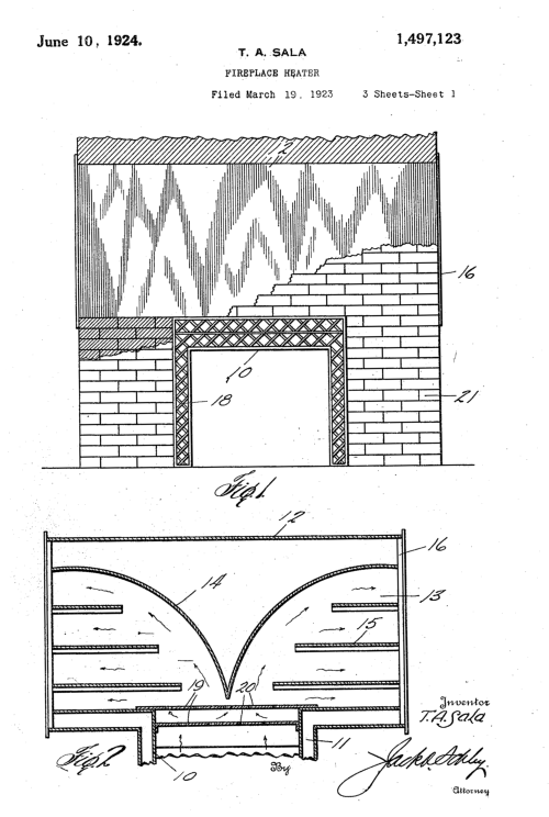
 Fireplace Heater Patent
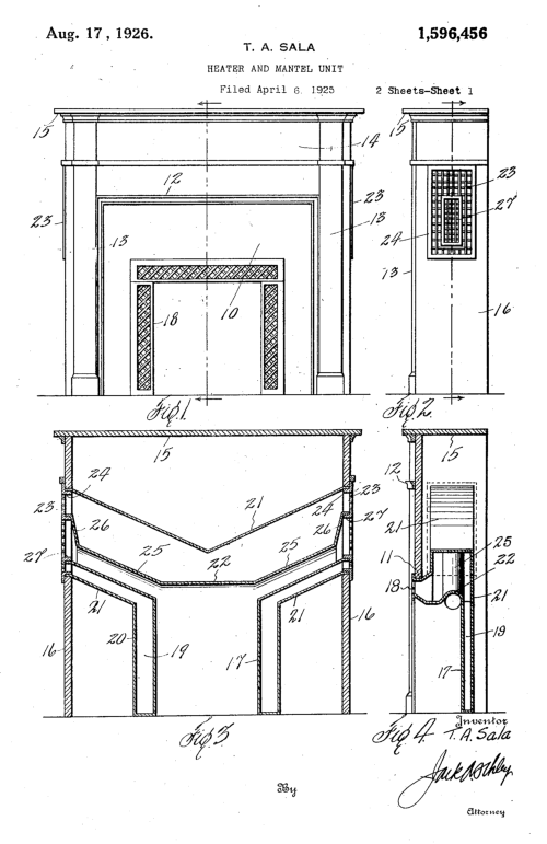
 Heater and Mantel Unit
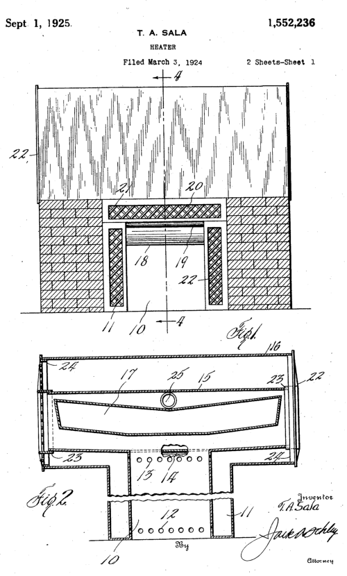
 Heater
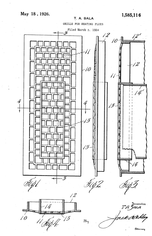
 Grille and Heating Flues
 Gas Log Heater

 Gas Mixing Unit
 Portable Heating Unit
 Gas Burners

 Multiple Flue Heater
 Heater Grille
Combo Heating Structure
Heater Grille
Combo Heating Structure
 Air Flue for Refrigeration
 Refrigerator Display
 Refrigerator Case
 Heater and Mantel Unit
Fireplace Heater Patent
SALA PATENTS
Refrigerator Case Patent
Heater and Mantel Unit
Fireplace Heater Patent
SALA PATENTS
Refrigerator Case Patent
 Patented August 25 ,1925. 1,551,120
UNITED STATES PATENT OFFICE.
THEODORE A. SALA, OF DALLAS, TEXAS.
DISPLAY REFRIGERATOR CASE
Application filed March 24, 1924. Serial No. 701,299.
To all whom it may concern:
Be it know that I, THEODORE A. SALA, citizen of
the United States of America, residing at Dallas, in the
county of Dallas and State of Texas have invented
certain new and useful Improvements in Display
Refrigerator Cases, of which the following is a
specification.
This invention relates to new and useful
improvements in display refrigerator cases.
The invention has to do with that type of
refrigerator which is generally used as a counter in
stores and markets and comprises refrigerator
compartments at end communication with an
intermediate display chamber which occupies a major
portion of the length of the case. It is customary to
place shelves in these chambers and to use
receptacles in the refrigerating compartments
containing ice and brine water or other cooling solutions
for making temperatures below freezing.
These receptacles are generally comparatively
large and but one is provided in each refrigerator
compartment, for each compartment or section of the
display chamber. As the cooling solution in the
receptacle evaporates or is carried off, its level is
lowered and the coldest air stratum being directly over
the solution, consequently the upper portion of the
refrigerator compartment becomes warm, as does the
upper part of the display chamber. As the liquid solution
level descends, the temperature at the top of the
chamber rises. To lower the temperature the receptacle
must be re-iced and even then there will be an area at
the top of the display chamber which is not as cold as
lower areas, because the receptacle may not reach the
top of the refrigerator or it may not be filled to its top.
These arrangements do not provide a uniform
temperature in the display chamber, are not economical
and fail to give as much efficiency as is obtainable.
It is the object of my invention to provide means
in the refrigerator compartment of a display refrigerator
case, for maintaining a nearly uniform temperature
below freezing or at the desired degree and for realizing
as much benefit from the cooling solution, at the top as
is received at the bottom
of the refrigerator compartment and display
chamber.
A further object is to provide a plurality of
comparatively small receptacles at different elevations
in the refrigerating compartment, preferably regularly
spaced or in close relation, whereby the cooling
solution acts directly upon the circulating air equally at
the top, center and bottom of the compartment; and
whereby the receptacles may be interchanged from one
elevaation to the other or individually re-iced all of
which makes for greater efficiency and economy.
A construction designed to carry out the invention
will be hereinafter described together with other
features of the invention.
The invention will be more readily understood
from a reading of the following specification and by
reference to the accompanying drawings, in which an
example of the invention is shown, and wherein:
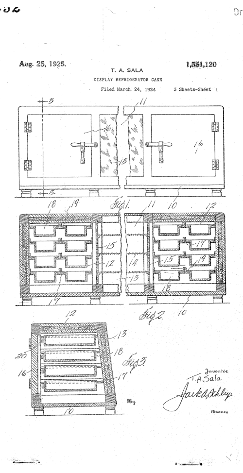
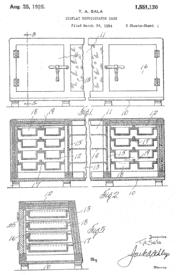
Fig. 1 is a fragmentary rear elevation of a case
constructed in accordance with my invention,
Fig. 2 is a longitudinal vertical sectional view of
the same,
Fig. 3 is a transverse vertical sectional view
taken on the line 3-3 of Fig. 1,
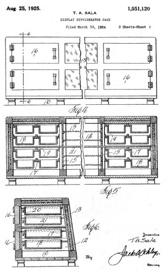
Fig. 4 is a rear elevation of a modified form,
Fig. 5 is a longitudinal vertical sectional view of
the same,
Fig. 6 is a transverse vertical sectional view on
the line 6-6 of Fig. 4,
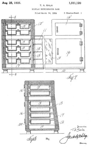
Fig. 7 is a fragmentary rear view of a modified
form case, partly in elevation and partly in section, and
Fig. 8 is a transverse vertical sectional view on
the lin 8-8 of Fig. 7.
In the drawing the numberal 10 designates the
base of a case which has a central or intermediate
display chamber 11 of the usual type and refrigerating
compartments 12 at each end, all having their tops
flush to form a counter. The chamber 11 has a glass
front 13 and may be provided with a plurality of
superposed foraminous shelves 14, through which the
air will circulate. Between each end of the display
chamber 11 and the contiguous refrigerator
compartment 12 is a vertical foraminous partition 15.
Each compartment has a rear door 16,
Patented August 25 ,1925. 1,551,120
UNITED STATES PATENT OFFICE.
THEODORE A. SALA, OF DALLAS, TEXAS.
DISPLAY REFRIGERATOR CASE
Application filed March 24, 1924. Serial No. 701,299.
To all whom it may concern:
Be it know that I, THEODORE A. SALA, citizen of
the United States of America, residing at Dallas, in the
county of Dallas and State of Texas have invented
certain new and useful Improvements in Display
Refrigerator Cases, of which the following is a
specification.
This invention relates to new and useful
improvements in display refrigerator cases.
The invention has to do with that type of
refrigerator which is generally used as a counter in
stores and markets and comprises refrigerator
compartments at end communication with an
intermediate display chamber which occupies a major
portion of the length of the case. It is customary to
place shelves in these chambers and to use
receptacles in the refrigerating compartments
containing ice and brine water or other cooling solutions
for making temperatures below freezing.
These receptacles are generally comparatively
large and but one is provided in each refrigerator
compartment, for each compartment or section of the
display chamber. As the cooling solution in the
receptacle evaporates or is carried off, its level is
lowered and the coldest air stratum being directly over
the solution, consequently the upper portion of the
refrigerator compartment becomes warm, as does the
upper part of the display chamber. As the liquid solution
level descends, the temperature at the top of the
chamber rises. To lower the temperature the receptacle
must be re-iced and even then there will be an area at
the top of the display chamber which is not as cold as
lower areas, because the receptacle may not reach the
top of the refrigerator or it may not be filled to its top.
These arrangements do not provide a uniform
temperature in the display chamber, are not economical
and fail to give as much efficiency as is obtainable.
It is the object of my invention to provide means
in the refrigerator compartment of a display refrigerator
case, for maintaining a nearly uniform temperature
below freezing or at the desired degree and for realizing
as much benefit from the cooling solution, at the top as
is received at the bottom
of the refrigerator compartment and display
chamber.
A further object is to provide a plurality of
comparatively small receptacles at different elevations
in the refrigerating compartment, preferably regularly
spaced or in close relation, whereby the cooling
solution acts directly upon the circulating air equally at
the top, center and bottom of the compartment; and
whereby the receptacles may be interchanged from one
elevaation to the other or individually re-iced all of
which makes for greater efficiency and economy.
A construction designed to carry out the invention
will be hereinafter described together with other
features of the invention.
The invention will be more readily understood
from a reading of the following specification and by
reference to the accompanying drawings, in which an
example of the invention is shown, and wherein:
Fig. 1 is a fragmentary rear elevation of a case
constructed in accordance with my invention,
Fig. 2 is a longitudinal vertical sectional view of
the same,
Fig. 3 is a transverse vertical sectional view
taken on the line 3-3 of Fig. 1,
Fig. 4 is a rear elevation of a modified form,
Fig. 5 is a longitudinal vertical sectional view of
the same,
Fig. 6 is a transverse vertical sectional view on
the line 6-6 of Fig. 4,
Fig. 7 is a fragmentary rear view of a modified
form case, partly in elevation and partly in section, and
Fig. 8 is a transverse vertical sectional view on
the lin 8-8 of Fig. 7.
In the drawing the numberal 10 designates the
base of a case which has a central or intermediate
display chamber 11 of the usual type and refrigerating
compartments 12 at each end, all having their tops
flush to form a counter. The chamber 11 has a glass
front 13 and may be provided with a plurality of
superposed foraminous shelves 14, through which the
air will circulate. Between each end of the display
chamber 11 and the contiguous refrigerator
compartment 12 is a vertical foraminous partition 15.
Each compartment has a rear door 16,


 Patent # 01551120
but one or more doors may be used. All of the parts
which have been described are common in the art and
no separate claim is made thereto.
In carrying out the invention I mount a plurality of
angular guide rails 17 transversely of each compartment
12 which extend from front to rear. These rails are
mounted in pairs at different elevations, two pairs to
each elevation. Between each pair of rails is suspended
a drawer of rectangular receptacle 18 each having out-
turned flanges 19 at its upper side edges, resting on the
rails. Each drawer has a handle 20, by which it may be
grasped and slid out the rear side of the compartment
when the door 16 is open.
This is true of all the figures of the drawings. In
Figs 1 to 3 incluseive, I have shown eight drawers to a
compartment, two at each elevation. These drawers are
filled with any kind of a refrigeration solution or liquid,
such as cracked ice and drine water and the like. It will
be seen that the upper drawers are close to the top of
the compartment, while the lower drawers are close to
the bottom. The four intermediate drawers are spaced
between the top and bottom drawers and provide a
cooling influence for this area.
All of the drawers supply the same compartment
of the display chamber and there is just as much
refrigeration at the top as there is at the bottom. This is
important as the air cooled by the upper drawers
circulates directly into the upper portion of the display
chamber, thus cooling and maintaining a low
temperature. Usually in a compartment such as I have
illustrated two refrigerating receptacles are used. It will
be seen that with such large receptacles, the level of the
refrigerating liquid will be reduced by evaporation and a
large upper space, without direct refrigeration, is
constantly being made.
Even with the drawers half filled with liquid direct
refrigeration is had at the top of the compartments 12
and chamber 11. The drawers are all interchangeable.
For instance after a period of time the top drawers may
be interchanged with the bottom drawers, as the liquid
in the top drawers may have a tendency to evaporate
faster thatn the liquid in the bottom drawers. Any drawer
ma be refilled and only one or two drawers may require
refilling at a time. This is much more economical and
efficient.
The invention permits of considerable variation.
For instance a butcher or store keeper may require
more display and storage space on some days than on
others, so that it will be economical to reduce the
refrigerating space and the quantity of liquid used. In
Figs. 4, 5 and 6 I have shown a case with a central
longitudinally
partition 21, extending from end to end through the
compartments 12, and the chamber 11. This partition
divides the case into two units or sections, one above
the other, other wise it is the same as that shown in Fig.
2. The four upper drawers in the upper sections of the
compartments 12 refrigerate the upper section of the
chamber 11, while the four lower drawers refrigerate the
lower section of the chamber. However both the upper
and lower sections of the chamber have direct
refrigeration at the upper portions. Either the upper or
lower section may be used individually when desired.
The idea of uniform refrigeration is carried out in this
form also.
Under certain conditions, it may be desirable to
surmount extensions 12' on the compartments 12 as is
shown in Figs. 7 and 8 and build the same above the
chamber 11. These extensions are entirely enclosed
and provided with separate doors 16'. In the extensions
are entirely enclosed and provided with separate doors
16'. In the extensions are mounted rails 17' carrying
drawers 18'. These additional drawers above the
display chamber would materially reduce the
temperature at the top of said chamber. This form would
probably prove quite economical because of the
number of drawers which could be interchanged. The
brine solution does not flow from the drawers and the
same are "non-flowing".
Various changes in the size and shape of the
different parts, as well as modifications and alterations,
may be made within the scope of the appended claims.
What I claim, is:
1. In a refrigerating display case, the combination
of a display chamber, a refrigerating compartment at
one end of the chamber, and a plurality of superposed
containers removably mounted within said compartment
and interchangeable, whereby each container may be
transposed from one elevation to another elevation in
said compartment.
2. In a refrigerator display case, the combination
of a display chamber, a refrigerating compartment at
one end of the chamber communicating therewith, and
a plurality of relatively small superposed containers
removably mounted in said compartment and being
interchangeable, whereby said containers may be
moved from one elevation to another elevation in said
compartment.
3. In a refrigerating display case, the combination
of a display chamber, a refrigeratng compartment at
one end of the case, and a plurality of refrigerating
receptacles removably mounted at different elevations
in said compartment, said receptacles being
interchangeable, whereby those at different elevations
may be transposed.
4. In a refrigerating display case, the combination
Patent # 01551120
but one or more doors may be used. All of the parts
which have been described are common in the art and
no separate claim is made thereto.
In carrying out the invention I mount a plurality of
angular guide rails 17 transversely of each compartment
12 which extend from front to rear. These rails are
mounted in pairs at different elevations, two pairs to
each elevation. Between each pair of rails is suspended
a drawer of rectangular receptacle 18 each having out-
turned flanges 19 at its upper side edges, resting on the
rails. Each drawer has a handle 20, by which it may be
grasped and slid out the rear side of the compartment
when the door 16 is open.
This is true of all the figures of the drawings. In
Figs 1 to 3 incluseive, I have shown eight drawers to a
compartment, two at each elevation. These drawers are
filled with any kind of a refrigeration solution or liquid,
such as cracked ice and drine water and the like. It will
be seen that the upper drawers are close to the top of
the compartment, while the lower drawers are close to
the bottom. The four intermediate drawers are spaced
between the top and bottom drawers and provide a
cooling influence for this area.
All of the drawers supply the same compartment
of the display chamber and there is just as much
refrigeration at the top as there is at the bottom. This is
important as the air cooled by the upper drawers
circulates directly into the upper portion of the display
chamber, thus cooling and maintaining a low
temperature. Usually in a compartment such as I have
illustrated two refrigerating receptacles are used. It will
be seen that with such large receptacles, the level of the
refrigerating liquid will be reduced by evaporation and a
large upper space, without direct refrigeration, is
constantly being made.
Even with the drawers half filled with liquid direct
refrigeration is had at the top of the compartments 12
and chamber 11. The drawers are all interchangeable.
For instance after a period of time the top drawers may
be interchanged with the bottom drawers, as the liquid
in the top drawers may have a tendency to evaporate
faster thatn the liquid in the bottom drawers. Any drawer
ma be refilled and only one or two drawers may require
refilling at a time. This is much more economical and
efficient.
The invention permits of considerable variation.
For instance a butcher or store keeper may require
more display and storage space on some days than on
others, so that it will be economical to reduce the
refrigerating space and the quantity of liquid used. In
Figs. 4, 5 and 6 I have shown a case with a central
longitudinally
partition 21, extending from end to end through the
compartments 12, and the chamber 11. This partition
divides the case into two units or sections, one above
the other, other wise it is the same as that shown in Fig.
2. The four upper drawers in the upper sections of the
compartments 12 refrigerate the upper section of the
chamber 11, while the four lower drawers refrigerate the
lower section of the chamber. However both the upper
and lower sections of the chamber have direct
refrigeration at the upper portions. Either the upper or
lower section may be used individually when desired.
The idea of uniform refrigeration is carried out in this
form also.
Under certain conditions, it may be desirable to
surmount extensions 12' on the compartments 12 as is
shown in Figs. 7 and 8 and build the same above the
chamber 11. These extensions are entirely enclosed
and provided with separate doors 16'. In the extensions
are entirely enclosed and provided with separate doors
16'. In the extensions are mounted rails 17' carrying
drawers 18'. These additional drawers above the
display chamber would materially reduce the
temperature at the top of said chamber. This form would
probably prove quite economical because of the
number of drawers which could be interchanged. The
brine solution does not flow from the drawers and the
same are "non-flowing".
Various changes in the size and shape of the
different parts, as well as modifications and alterations,
may be made within the scope of the appended claims.
What I claim, is:
1. In a refrigerating display case, the combination
of a display chamber, a refrigerating compartment at
one end of the chamber, and a plurality of superposed
containers removably mounted within said compartment
and interchangeable, whereby each container may be
transposed from one elevation to another elevation in
said compartment.
2. In a refrigerator display case, the combination
of a display chamber, a refrigerating compartment at
one end of the chamber communicating therewith, and
a plurality of relatively small superposed containers
removably mounted in said compartment and being
interchangeable, whereby said containers may be
moved from one elevation to another elevation in said
compartment.
3. In a refrigerating display case, the combination
of a display chamber, a refrigeratng compartment at
one end of the case, and a plurality of refrigerating
receptacles removably mounted at different elevations
in said compartment, said receptacles being
interchangeable, whereby those at different elevations
may be transposed.
4. In a refrigerating display case, the combination
 History
Sala Heater and Mantel Co.
Go Back to: History of Sala Heaters
Go Back to: Sala Patents
CALL TODAY! 214-742-7252
Dallas Air Conditioning Repair
AIR CONDITIONING SERVICE DALLAS TX
History
Sala Heater and Mantel Co.
Go Back to: History of Sala Heaters
Go Back to: Sala Patents
CALL TODAY! 214-742-7252
Dallas Air Conditioning Repair
AIR CONDITIONING SERVICE DALLAS TX


 Home | Products | Services | Coupons | Contracting | Contact | News Blog | Service Area | About Us | Sitemap
Service Areas: Dallas, Duncanville, DeSoto, Cedar Hill, Lancaster, Highland Park, Grand Prairie, Carrollton, Irving, Addison,
Garland, Coppell, Southlake, Grapevine, Sunnyvale, Richardson, Farmers Branch, Allen, Parker, Lucas, Frisco, Lewisville,
Flower Mound, Rowlett, Rockwall, Sachse, The Colony, University Park, Wylie, Murphy, Mansfield, Mesquite, Midlothian,
Ovilla, Red Oak, Hutchins, Lake Highlands, Lakewood, Preston Hollow, Oak Lawn, and Plano
Home | Products | Services | Coupons | Contracting | Contact | News Blog | Service Area | About Us | Sitemap
Service Areas: Dallas, Duncanville, DeSoto, Cedar Hill, Lancaster, Highland Park, Grand Prairie, Carrollton, Irving, Addison,
Garland, Coppell, Southlake, Grapevine, Sunnyvale, Richardson, Farmers Branch, Allen, Parker, Lucas, Frisco, Lewisville,
Flower Mound, Rowlett, Rockwall, Sachse, The Colony, University Park, Wylie, Murphy, Mansfield, Mesquite, Midlothian,
Ovilla, Red Oak, Hutchins, Lake Highlands, Lakewood, Preston Hollow, Oak Lawn, and Plano