Fireplace Heater PatentHeater and Mantel UnitHeaterGrille and Heating FluesGas Log HeaterGas Mixing UnitPortable Heating UnitGas BurnersMultiple Flue HeaterHeater GrilleCombo Heating StructureAir Flue for Refrigeration Refrigerator DisplayRefrigerator CaseHeater and Mantel UnitFireplace Heater PatentSALA PATENTSRefrigerator Display Case PatentPatented Sept. 1,1925. 1,552,237UNITED STATES PATENT OFFICE.THEODORE A. SALA, OF DALLAS, TEXAS.REFRIGERATOR DISPLAY CASEApplication filed August 15, 1924. Serial No. 732,267.To all whom it may concern:Be it know that I, THEODORE A. SALA, citizen of the United States of America, residing at Dallas, in the county of Dallas and State of Texas have invented certain new and useful Improvements in Refrigerator Display Cases, of which the following is a specification.This invention relates to new and useful improvements in refrigerator display cases.The invention has particularly to do with that type of display case which is used in stores and markets for displaying perishable articles of food such as meats, eggs, butter and the like; the case in most instances serving as a counter and the ice chamer being conealed at one or both ends.Such cases are frequently opened, and there is thus admitted warm air. The cold air settles to the bottom of the case and the warm air rises to the top and froms a blanket. For this reason only the lower shelf of bottom of the case now in common use can be used for the storage of foods requiring a freezing or very low temperature. Tests have shown that in the average refrigerator case the temperature on the bottom shelf would be approximately 32 degrees Fahrenheit, while the temperature on the top shelf would register from 45 to 65 degrees Fahrenheit. It is customary in some types of cases to have the brine solution pass to a tray under the display chamber. Such a practice creates too much moisture in the display chamber, where it is highly desirable to have the air of an even range of tempertures and as dry as possible.The object of the invention is to provide a refrigerator display case in which an even range of temperatures may be maintained and more efficient refrigerating obtained.An important object is to maintain the entire display chamber at a low range of temperatures, say from 28 degrees Fahrenheit on the bottom shelf to 35 to 40 degrees, Fahrenheit, on the top shelf, the variation being confined to a short length.Another object is to maintain a low or freezing temperature across the entire bottom shelf, even at a point remote from the ice chamber.A particular object is to cool the air or produce a low temperature in the displaychamber, by circulation instead of radiation or mere heat exchange, and to utilize the variation in the temperatures of the air stratas at different elevations in the display chamber, as well as the warm air admitted by opening the doors, to promote circulation through the ice chamber and thus maintain a range of low temperatures which will be substantially constant and subject to little variation.It is well known that the condition of the air has much to do with the degree of temperature, at which certain foods, such as meats, must be kept; and where the air is so called "dry" at higher temperature will preserve them, better than a low temperature and so called "wet" air. One of the dominant objects of my invention is to prevent the passage of liquid to or under the display chamber from the ice chamber and to supply the display chamber with cold "dry" air.A construction designed to carry out the invention will be hereinafter described together with other features of the invention. The invention will be more readily understood from a reading of the following specification and by reference to the accompanying drawings, in which an example of the invention is shown, and wherein:Fig. 1 is a longitudinal vertical sectional view of a refrigerator display case constructed in accordance with my invention,Fig. 2 is a horizontal cross sectional view on the line 2-2 of Fig.1, Fig. 3 is a transverse vertical sectional view on the line 3-3 of Fig. 1,Fig. 4 is a longitudinal vertical sectional view of a modified form, andFig. 5 is a similar view of another modification.In the drawings the numeral 10 designates the bottom of the refrigeration case, 11 the rear wall, 12 the front wall and 13 the end walls, all of which may be suitably constructed in accordance with the usual practice in this art or as the specific necessity may require; such walls usually being of several vertical sections of wood, metal, and insulating material, as well as glass panels.In carrying out my invention it is necessary to circulate the air and in order that no blanket or strata of dormant air may remain in the display chamber, the icePatent # 01552237chamber is extended above the same. I have shown in Figs. 1 to 3, an ice chamber 14 at each end of the case. The top 15 of each ice chamber extends several inches above the top 16 of the display chamber 17 which is disposed between said ice chambers. The top 16 is formed of spaced glass plates, while a similarly constructed panel 18 inclined in the front wall 12, forms the front of the display chamber. Doors 19 give access to the ice chamber; while doors 20 in the rear wall 11, ar provided for the display chamber.At each end of the diplay chamber is provided a vertical partition wall 21 terminating just above the bottom 10 and extending up into the top of the elevated portion of the ice chamber, which thus overhangs said wall. The upper end of the wall terminates below the top 16, thus forming an opening 22 and a duct 23 leading from the display chamber up to the said opening. Between the bottom of each partition wall 21 and the bottom 10 is formed an opening 24. It is important that the partition walls be imperforate as well as being insulated so that the heat exchange therethrough, is reduced to a negative degree.perforated or equivalent bottom shelf 25 has its ends secured to the bottom of the partitions and extends across the display chamber. This shelf is spaced above the bottom 10, whereby a flue 26 is formed. An intermediate forminous shelf 27 and a similar top shelf 28, are supported in the display chamber. Access to these shelves is had by opening the doors 20.Ice may be placed in the chambers 14 in any suitable manner, but I have found it satisfactory to mount in each chamber, a vertical rack 29 having horizontal rails 30 extending from the front to the rear of said chamber, but spaced from the walls thereof. In Figs. 1, 2 and 3 I have shown two paris of such rails supporting metal drawers 31, in superposed relation. These drawers may be suitably contructed and can be withdrawn by opening the doors 19. The drawers are spacer apart so as to provide ample space for circulation theraround. It is preferable to have the top of the upper drawer below the opening 22 in each chamber.In operation the air in the case will circulate, due to displacement by change in temperature. Cold air settles or moves downward, particularly as its temperature is lowered, while warm air rises or moves upward. The drawers 31 being iced, which usually consists in partially filling the same with brine water and then completing with ice, the temperature is gradually lowered. This causes the cold air to moved downward in the ice chambers 14 and pass out through the openings 24 to the flue 26. This cold air passes up through the perforated shell 25 into the display chamber 17. The warm air in the display chamber rises, passes up through the channels 23 at each end of the chamber 17 and enters the ice chambers 14 through the openings 22.The hottest air is at the top of the channels 23 and at this point is brought under the cooling influence of the ice chamber, thus the air can move in one direction only and that is up through the display chamber and down through the ice chambers. Each time a door is opened, warm air will be admitted and this will accelerate the circulation. The circulation will be more of less rapid and will create a draft up through the channels 23, which will draw the warm air from the top of the display chamber so it will be constantly replaced by air of a lower temperature. The insulated partitions prevent such heat exchange as would tend to retard the circulation.The circulation will not only keep the display chamber supplied with cold air at a low temperature, but will promote such evaporation that the air entering the flue 26 from the ice chambers will be free from excess moisture and will be substantially "dry" as it is known in this art. Experiments have shown that a substantially even temperature is had clear across the bottom shelf 25 and the temperature at the center is substantially the same as at the ends. Tests have been made showing a temperature of 28 degrees Fahrenheit entirely across the bottom shelf. Owing to the circulation the cold air will be carried to a higher elevation in the display chamber, than is usually obtained when radiation is depended upon and the wall between the ice and display chambers is not insulated and has openings. The result in the present instance is a lower temperature at the shelf 28 and a much lower temperature at the shelf 27, than is possible with other refrigerator cases.in the present instance is a lower temperature at the shelf 28 and a much lower temperature at the shelf 27, than is possible with other refrigerator cases.Warm air admitted when the doors 20 are opened is quickly displaced and does not effect the change in temperature usually had. In this invention where a temperature of 28 degrees Fahrenheit is had at the bottom shelf, a temperature of from 38 to 40 degrees Fahrenheit is found at the top shelf 28. In tests made of cases now in common use, where the air passes direct into the display chamber from the ice chamber without cirulation, it has been found that without a temperature of 28 degrees, Fahrenheit on the bottom shelf, next to the ice chamber, the temperature at the center of said shelf will be several degrees high and the temperature at the top shelf will range from 45 to 65 degrees Fahrenheit. Tests have also shown that after standing for several hours, as overnight, both the bottom of the flue 26 and the bottom of the ice chambers, were free from moisture.In Fig. 4 I have shown a modified form in which the ice chamber at one end is omitted and the display chamber 17 is closed at this end by an insulating wal 13'. In the ice chamber, a greater number of drawers 31' are shown mounted in a suitable rack 29' on rails 30'; however the drawer arrangement is optional. The bottom shelf 25 and the other arrangements air the same. In this type the cold air will pass along the flue 26 and up through the perforations into the display chamber. Repeated tests have produced the same temperature at each end of the chamber 17. In Fig. 5 another form is shown which differs only in the bottom shelf, a portion 25' of which is imperforate and a section 26', remote from the ice chamber, is perforated. The length of the perforated section may vary. This form is found to enhance the circulation and has advantages for some purposes.It is important that the partitions extend above the display chamber and the channels be provided between the partitions and the display chamber, so that the air can no escape into the ice chamber below the top of the ice receptacle. It is very important that no liquid be conducted or permitted to pass into the flue 26 below the display chamber. The refrigerating receptacles should also be distributed vertically of the ice chambers and no open brine trays should be used on the bottom of the ice chmabers. There should be no obstructions between the upper strata of the air in the display chamber and the channel leading to ice chamber.While I have set fourth the advantage of excluding liquids from the flue 26, under the display chamber and obviation the use of brine trays in the bottom of the display chamber, it is to be understood that such trays may be used as the circulation which is had with my invention will improve the refrigerating qualities of any case and the invention contemplates both the use and the omission of such trays, or solutions.Various changes in the size and shape of the different parts, as well as modifications and variations may be made within the scope of the appended claims.What I claim is:1. In a refrigerator case, a display chamber, a refrigerating chamber at one end of the display chamber extending above the top of the display chamber, an imperforate insulating partition between the chambers, the upper end of the refrigerating chamber overhanging the partition, a vertical passage leading directly from the adjacent end of the display chamber up to the side of the partition, there being an opening between the upper end of the passage and the ice chamber, the partition terminating near the bottom of the ice chamber, there being an opening under the partition between chambers.2. In a refrigerator case, a display chamber, a vertical refrigerating chamber having its upper end extending above the display chamber, an imperforate partition separating the chambers and extending into the upper end of the refrigerating chamber above the display chamber and spaced from the side wall of the refrigerating chamber, a vertical air passage extending from the adjacent upper end of the diplay chamber to the top of the refrigerating chamber, the lower end of the passage opening into the display chamber, the top of the partition terminating near the top of the partition terminating near the top of the refrigerating chamber, there being an air passage between the top of the partition and the top of the refrigerating chamber, connecting with the vertical air passage, the partition having its lower end terminating immediately over the bottom of the case and providing an outlet at the bottom of the refrigerating chamber, and an air conducting flue leading from said outlet in the bottom of the display chamber.3. In a refrigerator case, the combination of a display chamber, a vertical refrigerating chamber having its upper end extending above the display chamber, an imperforate partition separating the chambers and extending into the upper end of the refrigerating chamber above the display chamber and spaced from the side wall of the refrigerating chamber to provide a vertical passage extending form the adjacent end of the display chamber, the top of the refrigerating chamber, there being an air passage between the top of the partition and the top of the refrigerating chamber connecting with the vertical air passage, the partition having its lower end terminating immediately over the bottom of the case and providing an outlet at the bottom of the refrigerating chamber, an air conducting flue leading from said outlet in the bottom of the display chamber, and removable ice receptacles in the refrigerating chamber separate from said partition, the space above the receptacles at the top of the refrigerating chamber being free for the circulation of air currents.In testimony whereof I affix my signatureTHEODORE A. SALA.HistorySala Heater and Mantel Co.Go Back to: History of Sala HeatersGo Back to: Sala PatentsCALL TODAY! 214-742-7252Dallas Air Conditioning RepairAIR CONDITIONING SERVICE DALLAS TXHome | Products | Services | Coupons | Contracting | Contact | News Blog | Service Area | About Us |SitemapService Areas: Dallas, Duncanville, DeSoto, Cedar Hill, Lancaster, Highland Park, Grand Prairie, Carrollton, Irving, Addison, Garland, Coppell, Southlake, Grapevine, Sunnyvale, Richardson, Farmers Branch, Allen, Parker, Lucas, Frisco, Lewisville, Flower Mound, Rowlett, Rockwall, Sachse, The Colony, University Park, Wylie, Murphy, Mansfield, Mesquite, Midlothian, Ovilla, Red Oak, Hutchins, Lake Highlands, Lakewood, Preston Hollow, Oak Lawn, and Plano


 Fireplace Heater Patent
 Heater and Mantel Unit
 Heater
 Grille and Heating Flues
 Gas Log Heater

 Gas Mixing Unit
 Portable Heating Unit
 Gas Burners

 Multiple Flue Heater
 Heater Grille
Combo Heating Structure
Heater Grille
Combo Heating Structure
 Air Flue for Refrigeration
 Refrigerator Display
 Refrigerator Case
 Heater and Mantel Unit
Fireplace Heater Patent
SALA PATENTS
Refrigerator Display Case Patent
Heater and Mantel Unit
Fireplace Heater Patent
SALA PATENTS
Refrigerator Display Case Patent
 Patented Sept. 1,1925.
1,552,237
UNITED STATES PATENT OFFICE.
THEODORE A. SALA, OF DALLAS, TEXAS.
REFRIGERATOR DISPLAY CASE
Application filed August 15, 1924. Serial No. 732,267.
To all whom it may concern:
Be it know that I, THEODORE A. SALA, citizen of
the United States of America, residing at Dallas, in the
county of Dallas and State of Texas have invented
certain new and useful Improvements in Refrigerator
Display Cases, of which the following is a specification.
This invention relates to new and useful
improvements in refrigerator display cases.
The invention has particularly to do with that type
of display case which is used in stores and markets for
displaying perishable articles of food such as meats,
eggs, butter and the like; the case in most instances
serving as a counter and the ice chamer being
conealed at one or both ends.
Such cases are frequently opened, and there is
thus admitted warm air. The cold air settles to the
bottom of the case and the warm air rises to the top and
froms a blanket. For this reason only the lower shelf of
bottom of the case now in common use can be used for
the storage of foods requiring a freezing or very low
temperature. Tests have shown that in the average
refrigerator case the temperature on the bottom shelf
would be approximately 32 degrees Fahrenheit, while
the temperature on the top shelf would register from 45
to 65 degrees Fahrenheit.
It is customary in some types of cases to have
the brine solution pass to a tray under the display
chamber. Such a practice creates too much moisture in
the display chamber, where it is highly desirable to have
the air of an even range of tempertures and as dry as
possible.
The object of the invention is to provide a
refrigerator display case in which an even range of
temperatures may be maintained and more efficient
refrigerating obtained.
An important object is to maintain the entire
display chamber at a low range of temperatures, say
from 28 degrees Fahrenheit on the bottom shelf to 35 to
40 degrees, Fahrenheit, on the top shelf, the variation
being confined to a short length.
Another object is to maintain a low or freezing
temperature across the entire bottom shelf, even at a
point remote from the ice chamber.
A particular object is to cool the air or produce a
low temperature in the display
chamber, by circulation instead of radiation or mere
heat exchange, and to utilize the variation in the
temperatures of the air stratas at different elevations in
the display chamber, as well as the warm air admitted
by opening the doors, to promote circulation through
the ice chamber and thus maintain a range of low
temperatures which will be substantially constant and
subject to little variation.
It is well known that the condition of the air has
much to do with the degree of temperature, at which
certain foods, such as meats, must be kept; and where
the air is so called "dry" at higher temperature will
preserve them, better than a low temperature and so
called "wet" air. One of the dominant objects of my
invention is to prevent the passage of liquid to or under
the display chamber from the ice chamber and to
supply the display chamber with cold "dry" air.
A construction designed to carry out the invention
will be hereinafter described together with other
features of the invention.
The invention will be more readily understood
from a reading of the following specification and by
reference to the accompanying drawings, in which an
example of the invention is shown, and wherein:
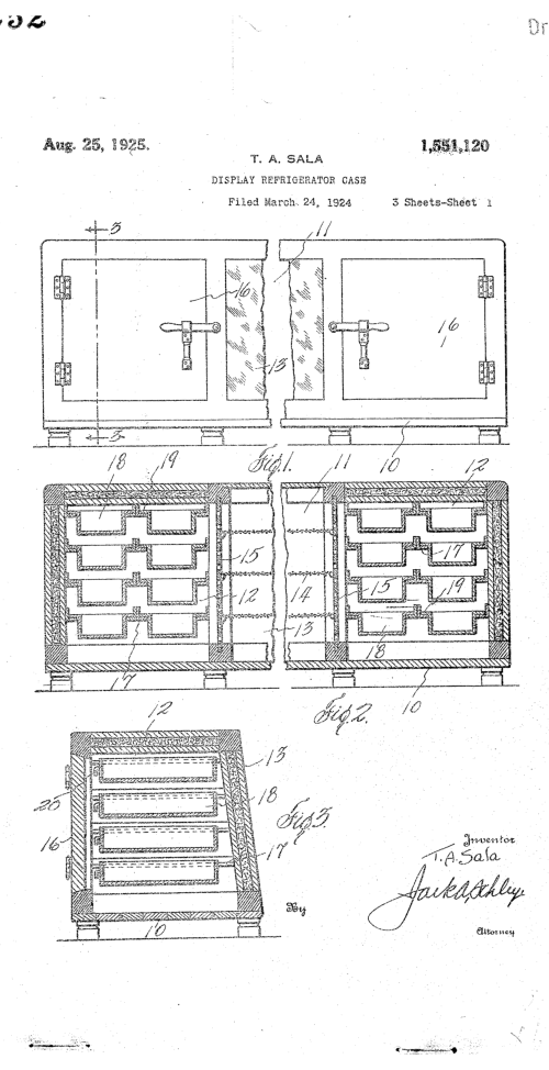
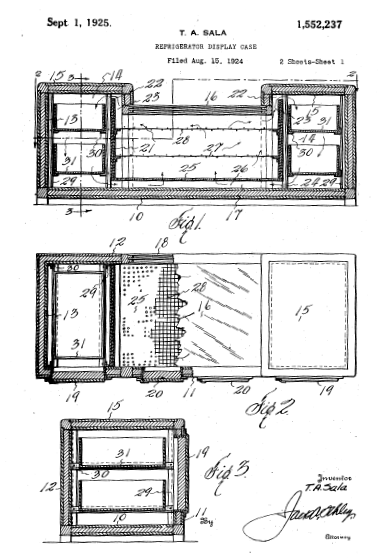
Fig. 1 is a longitudinal vertical sectional view of a
refrigerator display case constructed in accordance with
my invention,
Fig. 2 is a horizontal cross sectional view on the
line 2-2 of Fig.1,
Fig. 3 is a transverse vertical sectional view on
the line 3-3 of Fig. 1,
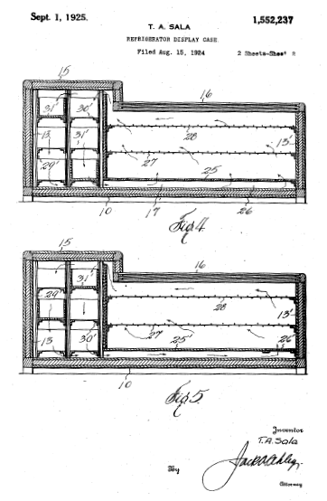
Fig. 4 is a longitudinal vertical sectional view of a
modified form, and
Fig. 5 is a similar view of another modification.
In the drawings the numeral 10 designates the
bottom of the refrigeration case, 11 the rear wall, 12 the
front wall and 13 the end walls, all of which may be
suitably constructed in accordance with the usual
practice in this art or as the specific necessity may
require; such walls usually being of several vertical
sections of wood, metal, and insulating material, as well
as glass panels.
In carrying out my invention it is necessary to
circulate the air and in order that no blanket or strata of
dormant air may remain in the display chamber, the ice
Patented Sept. 1,1925.
1,552,237
UNITED STATES PATENT OFFICE.
THEODORE A. SALA, OF DALLAS, TEXAS.
REFRIGERATOR DISPLAY CASE
Application filed August 15, 1924. Serial No. 732,267.
To all whom it may concern:
Be it know that I, THEODORE A. SALA, citizen of
the United States of America, residing at Dallas, in the
county of Dallas and State of Texas have invented
certain new and useful Improvements in Refrigerator
Display Cases, of which the following is a specification.
This invention relates to new and useful
improvements in refrigerator display cases.
The invention has particularly to do with that type
of display case which is used in stores and markets for
displaying perishable articles of food such as meats,
eggs, butter and the like; the case in most instances
serving as a counter and the ice chamer being
conealed at one or both ends.
Such cases are frequently opened, and there is
thus admitted warm air. The cold air settles to the
bottom of the case and the warm air rises to the top and
froms a blanket. For this reason only the lower shelf of
bottom of the case now in common use can be used for
the storage of foods requiring a freezing or very low
temperature. Tests have shown that in the average
refrigerator case the temperature on the bottom shelf
would be approximately 32 degrees Fahrenheit, while
the temperature on the top shelf would register from 45
to 65 degrees Fahrenheit.
It is customary in some types of cases to have
the brine solution pass to a tray under the display
chamber. Such a practice creates too much moisture in
the display chamber, where it is highly desirable to have
the air of an even range of tempertures and as dry as
possible.
The object of the invention is to provide a
refrigerator display case in which an even range of
temperatures may be maintained and more efficient
refrigerating obtained.
An important object is to maintain the entire
display chamber at a low range of temperatures, say
from 28 degrees Fahrenheit on the bottom shelf to 35 to
40 degrees, Fahrenheit, on the top shelf, the variation
being confined to a short length.
Another object is to maintain a low or freezing
temperature across the entire bottom shelf, even at a
point remote from the ice chamber.
A particular object is to cool the air or produce a
low temperature in the display
chamber, by circulation instead of radiation or mere
heat exchange, and to utilize the variation in the
temperatures of the air stratas at different elevations in
the display chamber, as well as the warm air admitted
by opening the doors, to promote circulation through
the ice chamber and thus maintain a range of low
temperatures which will be substantially constant and
subject to little variation.
It is well known that the condition of the air has
much to do with the degree of temperature, at which
certain foods, such as meats, must be kept; and where
the air is so called "dry" at higher temperature will
preserve them, better than a low temperature and so
called "wet" air. One of the dominant objects of my
invention is to prevent the passage of liquid to or under
the display chamber from the ice chamber and to
supply the display chamber with cold "dry" air.
A construction designed to carry out the invention
will be hereinafter described together with other
features of the invention.
The invention will be more readily understood
from a reading of the following specification and by
reference to the accompanying drawings, in which an
example of the invention is shown, and wherein:
Fig. 1 is a longitudinal vertical sectional view of a
refrigerator display case constructed in accordance with
my invention,
Fig. 2 is a horizontal cross sectional view on the
line 2-2 of Fig.1,
Fig. 3 is a transverse vertical sectional view on
the line 3-3 of Fig. 1,
Fig. 4 is a longitudinal vertical sectional view of a
modified form, and
Fig. 5 is a similar view of another modification.
In the drawings the numeral 10 designates the
bottom of the refrigeration case, 11 the rear wall, 12 the
front wall and 13 the end walls, all of which may be
suitably constructed in accordance with the usual
practice in this art or as the specific necessity may
require; such walls usually being of several vertical
sections of wood, metal, and insulating material, as well
as glass panels.
In carrying out my invention it is necessary to
circulate the air and in order that no blanket or strata of
dormant air may remain in the display chamber, the ice


 Patent # 01552237
chamber is extended above the same. I have shown in
Figs. 1 to 3, an ice chamber 14 at each end of the case.
The top 15 of each ice chamber extends several inches
above the top 16 of the display chamber 17 which is
disposed between said ice chambers. The top 16 is
formed of spaced glass plates, while a similarly
constructed panel 18 inclined in the front wall 12, forms
the front of the display chamber. Doors 19 give access
to the ice chamber; while doors 20 in the rear wall 11,
ar provided for the display chamber.
At each end of the diplay chamber is provided a
vertical partition wall 21 terminating just above the
bottom 10 and extending up into the top of the elevated
portion of the ice chamber, which thus overhangs said
wall. The upper end of the wall terminates below the top
16, thus forming an opening 22 and a duct 23 leading
from the display chamber up to the said opening.
Between the bottom of each partition wall 21 and the
bottom 10 is formed an opening 24. It is important that
the partition walls be imperforate as well as being
insulated so that the heat exchange therethrough, is
reduced to a negative degree.
perforated or equivalent bottom shelf 25 has its
ends secured to the bottom of the partitions and
extends across the display chamber. This shelf is
spaced above the bottom 10, whereby a flue 26 is
formed. An intermediate forminous shelf 27 and a
similar top shelf 28, are supported in the display
chamber. Access to these shelves is had by opening
the doors 20.
Ice may be placed in the chambers 14 in any
suitable manner, but I have found it satisfactory to
mount in each chamber, a vertical rack 29 having
horizontal rails 30 extending from the front to the rear of
said chamber, but spaced from the walls thereof. In
Figs. 1, 2 and 3 I have shown two paris of such rails
supporting metal drawers 31, in superposed relation.
These drawers may be suitably contructed and can be
withdrawn by opening the doors 19. The drawers are
spacer apart so as to provide ample space for
circulation theraround. It is preferable to have the top of
the upper drawer below the opening 22 in each
chamber.
In operation the air in the case will circulate, due
to displacement by change in temperature. Cold air
settles or moves downward, particularly as its
temperature is lowered, while warm air rises or moves
upward. The drawers 31 being iced, which usually
consists in partially filling the same with brine water and
then completing with ice, the temperature is gradually
lowered. This causes the cold air to moved downward in
the ice chambers 14 and pass out through the openings
24 to the flue 26. This cold air passes up through the
perforated shell 25 into the display chamber 17. The
warm air in the display chamber rises, passes up
through the channels 23 at each end of the chamber 17
and enters the ice chambers 14 through the openings
22.
The hottest air is at the top of the channels 23
and at this point is brought under the cooling influence
of the ice chamber, thus the air can move in one
direction only and that is up through the display
chamber and down through the ice chambers. Each
time a door is opened, warm air will be admitted and this
will accelerate the circulation. The circulation will be
more of less rapid and will create a draft up through the
channels 23, which will draw the warm air from the top
of the display chamber so it will be constantly replaced
by air of a lower temperature. The insulated partitions
prevent such heat exchange as would tend to retard the
circulation.
The circulation will not only keep the display
chamber supplied with cold air at a low temperature, but
will promote such evaporation that the air entering the
flue 26 from the ice chambers will be free from excess
moisture and will be substantially "dry" as it is known in
this art. Experiments have shown that a substantially
even temperature is had clear across the bottom shelf
25 and the temperature at the center is substantially the
same as at the ends. Tests have been made showing a
temperature of 28 degrees Fahrenheit entirely across
the bottom shelf. Owing to the circulation the cold air will
be carried to a higher elevation in the display chamber,
than is usually obtained when radiation is depended
upon and the wall between the ice and display
chambers is not insulated and has openings. The result
in the present instance is a lower temperature at the
shelf 28 and a much lower temperature at the shelf 27,
than is possible with other refrigerator cases.
Patent # 01552237
chamber is extended above the same. I have shown in
Figs. 1 to 3, an ice chamber 14 at each end of the case.
The top 15 of each ice chamber extends several inches
above the top 16 of the display chamber 17 which is
disposed between said ice chambers. The top 16 is
formed of spaced glass plates, while a similarly
constructed panel 18 inclined in the front wall 12, forms
the front of the display chamber. Doors 19 give access
to the ice chamber; while doors 20 in the rear wall 11,
ar provided for the display chamber.
At each end of the diplay chamber is provided a
vertical partition wall 21 terminating just above the
bottom 10 and extending up into the top of the elevated
portion of the ice chamber, which thus overhangs said
wall. The upper end of the wall terminates below the top
16, thus forming an opening 22 and a duct 23 leading
from the display chamber up to the said opening.
Between the bottom of each partition wall 21 and the
bottom 10 is formed an opening 24. It is important that
the partition walls be imperforate as well as being
insulated so that the heat exchange therethrough, is
reduced to a negative degree.
perforated or equivalent bottom shelf 25 has its
ends secured to the bottom of the partitions and
extends across the display chamber. This shelf is
spaced above the bottom 10, whereby a flue 26 is
formed. An intermediate forminous shelf 27 and a
similar top shelf 28, are supported in the display
chamber. Access to these shelves is had by opening
the doors 20.
Ice may be placed in the chambers 14 in any
suitable manner, but I have found it satisfactory to
mount in each chamber, a vertical rack 29 having
horizontal rails 30 extending from the front to the rear of
said chamber, but spaced from the walls thereof. In
Figs. 1, 2 and 3 I have shown two paris of such rails
supporting metal drawers 31, in superposed relation.
These drawers may be suitably contructed and can be
withdrawn by opening the doors 19. The drawers are
spacer apart so as to provide ample space for
circulation theraround. It is preferable to have the top of
the upper drawer below the opening 22 in each
chamber.
In operation the air in the case will circulate, due
to displacement by change in temperature. Cold air
settles or moves downward, particularly as its
temperature is lowered, while warm air rises or moves
upward. The drawers 31 being iced, which usually
consists in partially filling the same with brine water and
then completing with ice, the temperature is gradually
lowered. This causes the cold air to moved downward in
the ice chambers 14 and pass out through the openings
24 to the flue 26. This cold air passes up through the
perforated shell 25 into the display chamber 17. The
warm air in the display chamber rises, passes up
through the channels 23 at each end of the chamber 17
and enters the ice chambers 14 through the openings
22.
The hottest air is at the top of the channels 23
and at this point is brought under the cooling influence
of the ice chamber, thus the air can move in one
direction only and that is up through the display
chamber and down through the ice chambers. Each
time a door is opened, warm air will be admitted and this
will accelerate the circulation. The circulation will be
more of less rapid and will create a draft up through the
channels 23, which will draw the warm air from the top
of the display chamber so it will be constantly replaced
by air of a lower temperature. The insulated partitions
prevent such heat exchange as would tend to retard the
circulation.
The circulation will not only keep the display
chamber supplied with cold air at a low temperature, but
will promote such evaporation that the air entering the
flue 26 from the ice chambers will be free from excess
moisture and will be substantially "dry" as it is known in
this art. Experiments have shown that a substantially
even temperature is had clear across the bottom shelf
25 and the temperature at the center is substantially the
same as at the ends. Tests have been made showing a
temperature of 28 degrees Fahrenheit entirely across
the bottom shelf. Owing to the circulation the cold air will
be carried to a higher elevation in the display chamber,
than is usually obtained when radiation is depended
upon and the wall between the ice and display
chambers is not insulated and has openings. The result
in the present instance is a lower temperature at the
shelf 28 and a much lower temperature at the shelf 27,
than is possible with other refrigerator cases.
 in the present instance is a lower temperature at the
shelf 28 and a much lower temperature at the shelf 27,
than is possible with other refrigerator cases.
Warm air admitted when the doors 20 are
opened is quickly displaced and does not effect the
change in temperature usually had. In this invention
where a temperature of 28 degrees Fahrenheit is had
at the bottom shelf, a temperature of from 38 to 40
degrees Fahrenheit is found at the top shelf 28. In tests
made of cases now in common use, where the air
passes direct into the display chamber from the ice
chamber without cirulation, it has been found that
without a temperature of 28 degrees, Fahrenheit on the
bottom shelf, next to the ice chamber, the temperature
at the center of said shelf will be several degrees high
and the temperature at the top shelf will range from 45
to 65 degrees Fahrenheit. Tests have also shown that
after standing for several hours, as overnight, both the
bottom of the flue 26 and the bottom of the ice
chambers, were free from moisture.
In Fig. 4 I have shown a modified form in which
the ice chamber at one end is omitted and the display
chamber 17 is closed at this end by an insulating wal
13'. In the ice chamber, a greater number of drawers
31' are shown mounted in a suitable rack 29' on rails
30'; however the drawer arrangement is optional. The
bottom shelf 25 and the other arrangements air the
same. In this type the cold air will pass along the flue
26 and up through the perforations into the display
chamber. Repeated tests have produced the same
temperature at each end of the chamber 17. In Fig. 5
another form is shown which differs only in the bottom
shelf, a portion 25' of which is imperforate and a
section 26', remote from the ice chamber, is perforated.
The length of the perforated section may vary. This
form is found to enhance the circulation and has
advantages for some purposes.
It is important that the partitions extend above
the display chamber and the channels be provided
between the partitions and the display chamber, so that
the air can no escape into the ice chamber below the
top of the ice receptacle. It is very important that no
liquid be conducted or permitted to pass into the flue 26
below the display chamber. The refrigerating
receptacles should also be distributed vertically of the
ice chambers and no open brine trays should be used
on the bottom of the ice chmabers. There should be no
obstructions between the upper strata of the air in the
display chamber and the channel leading to ice
chamber.
While I have set fourth the advantage of excluding
liquids from the flue 26, under the display chamber and
obviation the use of brine trays in the bottom of the
display chamber, it is to be understood that such trays
may be used as the circulation which is had with my
invention will improve the refrigerating qualities of any
case and the invention contemplates both the use and
the omission of such trays, or solutions.
Various changes in the size and shape of the
different parts, as well as modifications and variations
may be made within the scope of the appended claims.
What I claim is:
1. In a refrigerator case, a display chamber, a
refrigerating chamber at one end of the display chamber
extending above the top of the display chamber, an
imperforate insulating partition between the chambers,
the upper end of the refrigerating chamber overhanging
the partition, a vertical passage leading directly from the
adjacent end of the display chamber up to the side of the
partition, there being an opening between the upper end
of the passage and the ice chamber, the partition
terminating near the bottom of the ice chamber, there
being an opening under the partition between chambers.
2. In a refrigerator case, a display chamber, a
vertical refrigerating chamber having its upper end
extending above the display chamber, an imperforate
partition separating the chambers and extending into the
upper end of the refrigerating chamber above the display
chamber and spaced from the side wall of the
refrigerating chamber, a vertical air passage extending
from the adjacent upper end of the diplay chamber to the
top of the refrigerating chamber, the lower end of the
passage opening into the display chamber, the top of the
partition terminating near the top of the partition
terminating near the top of the refrigerating chamber,
there being an air passage between the top of the
partition and the top of the refrigerating chamber,
connecting with the vertical air passage, the partition
having its lower end terminating immediately over the
bottom of the case and providing an outlet at the bottom
of the refrigerating chamber, and an air conducting flue
leading from said outlet in the bottom of the display
chamber.
3. In a refrigerator case, the combination of a
display chamber, a vertical refrigerating chamber having
its upper end extending above the display chamber, an
imperforate partition separating the chambers and
extending into the upper end of the refrigerating chamber
above the display chamber and spaced from the side
wall of the refrigerating chamber to provide a vertical
in the present instance is a lower temperature at the
shelf 28 and a much lower temperature at the shelf 27,
than is possible with other refrigerator cases.
Warm air admitted when the doors 20 are
opened is quickly displaced and does not effect the
change in temperature usually had. In this invention
where a temperature of 28 degrees Fahrenheit is had
at the bottom shelf, a temperature of from 38 to 40
degrees Fahrenheit is found at the top shelf 28. In tests
made of cases now in common use, where the air
passes direct into the display chamber from the ice
chamber without cirulation, it has been found that
without a temperature of 28 degrees, Fahrenheit on the
bottom shelf, next to the ice chamber, the temperature
at the center of said shelf will be several degrees high
and the temperature at the top shelf will range from 45
to 65 degrees Fahrenheit. Tests have also shown that
after standing for several hours, as overnight, both the
bottom of the flue 26 and the bottom of the ice
chambers, were free from moisture.
In Fig. 4 I have shown a modified form in which
the ice chamber at one end is omitted and the display
chamber 17 is closed at this end by an insulating wal
13'. In the ice chamber, a greater number of drawers
31' are shown mounted in a suitable rack 29' on rails
30'; however the drawer arrangement is optional. The
bottom shelf 25 and the other arrangements air the
same. In this type the cold air will pass along the flue
26 and up through the perforations into the display
chamber. Repeated tests have produced the same
temperature at each end of the chamber 17. In Fig. 5
another form is shown which differs only in the bottom
shelf, a portion 25' of which is imperforate and a
section 26', remote from the ice chamber, is perforated.
The length of the perforated section may vary. This
form is found to enhance the circulation and has
advantages for some purposes.
It is important that the partitions extend above
the display chamber and the channels be provided
between the partitions and the display chamber, so that
the air can no escape into the ice chamber below the
top of the ice receptacle. It is very important that no
liquid be conducted or permitted to pass into the flue 26
below the display chamber. The refrigerating
receptacles should also be distributed vertically of the
ice chambers and no open brine trays should be used
on the bottom of the ice chmabers. There should be no
obstructions between the upper strata of the air in the
display chamber and the channel leading to ice
chamber.
While I have set fourth the advantage of excluding
liquids from the flue 26, under the display chamber and
obviation the use of brine trays in the bottom of the
display chamber, it is to be understood that such trays
may be used as the circulation which is had with my
invention will improve the refrigerating qualities of any
case and the invention contemplates both the use and
the omission of such trays, or solutions.
Various changes in the size and shape of the
different parts, as well as modifications and variations
may be made within the scope of the appended claims.
What I claim is:
1. In a refrigerator case, a display chamber, a
refrigerating chamber at one end of the display chamber
extending above the top of the display chamber, an
imperforate insulating partition between the chambers,
the upper end of the refrigerating chamber overhanging
the partition, a vertical passage leading directly from the
adjacent end of the display chamber up to the side of the
partition, there being an opening between the upper end
of the passage and the ice chamber, the partition
terminating near the bottom of the ice chamber, there
being an opening under the partition between chambers.
2. In a refrigerator case, a display chamber, a
vertical refrigerating chamber having its upper end
extending above the display chamber, an imperforate
partition separating the chambers and extending into the
upper end of the refrigerating chamber above the display
chamber and spaced from the side wall of the
refrigerating chamber, a vertical air passage extending
from the adjacent upper end of the diplay chamber to the
top of the refrigerating chamber, the lower end of the
passage opening into the display chamber, the top of the
partition terminating near the top of the partition
terminating near the top of the refrigerating chamber,
there being an air passage between the top of the
partition and the top of the refrigerating chamber,
connecting with the vertical air passage, the partition
having its lower end terminating immediately over the
bottom of the case and providing an outlet at the bottom
of the refrigerating chamber, and an air conducting flue
leading from said outlet in the bottom of the display
chamber.
3. In a refrigerator case, the combination of a
display chamber, a vertical refrigerating chamber having
its upper end extending above the display chamber, an
imperforate partition separating the chambers and
extending into the upper end of the refrigerating chamber
above the display chamber and spaced from the side
wall of the refrigerating chamber to provide a vertical


 Home | Products | Services | Coupons | Contracting | Contact | News Blog | Service Area | About Us | Sitemap
Service Areas: Dallas, Duncanville, DeSoto, Cedar Hill, Lancaster, Highland Park, Grand Prairie, Carrollton, Irving, Addison,
Garland, Coppell, Southlake, Grapevine, Sunnyvale, Richardson, Farmers Branch, Allen, Parker, Lucas, Frisco, Lewisville,
Flower Mound, Rowlett, Rockwall, Sachse, The Colony, University Park, Wylie, Murphy, Mansfield, Mesquite, Midlothian,
Ovilla, Red Oak, Hutchins, Lake Highlands, Lakewood, Preston Hollow, Oak Lawn, and Plano
Home | Products | Services | Coupons | Contracting | Contact | News Blog | Service Area | About Us | Sitemap
Service Areas: Dallas, Duncanville, DeSoto, Cedar Hill, Lancaster, Highland Park, Grand Prairie, Carrollton, Irving, Addison,
Garland, Coppell, Southlake, Grapevine, Sunnyvale, Richardson, Farmers Branch, Allen, Parker, Lucas, Frisco, Lewisville,
Flower Mound, Rowlett, Rockwall, Sachse, The Colony, University Park, Wylie, Murphy, Mansfield, Mesquite, Midlothian,
Ovilla, Red Oak, Hutchins, Lake Highlands, Lakewood, Preston Hollow, Oak Lawn, and Plano